INSTALL MANUAL: Ranger/B4000, 2Dr Explorer, & GEN1 Sport Trac
INSTALLATION INSTRUCTIONS
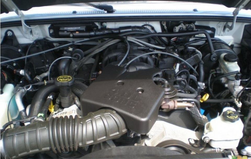
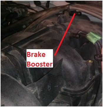
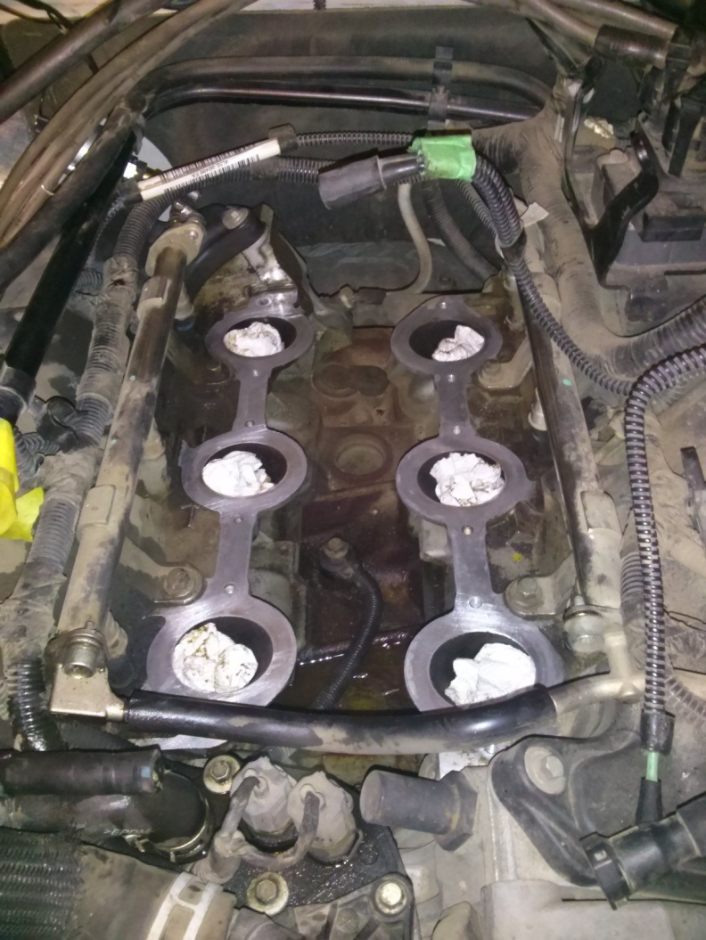
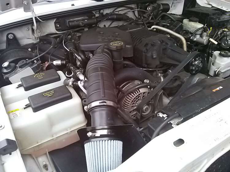
The following Installation Instructions apply to the 2001-2011 Ford Ranger / B4000 (earlier years in USA), 2002-2003 Ford Explorer 2-Door, and the 2002-2005 Ford Explorer Sport Trac 4.0L SOHC models. Prior to proceeding, confirm that your engine bay looks similar to the following photo:
You should read the entire instruction manual prior to proceeding with your installation.
It is important to familiarize yourself with the ModdBox Supercharger Kit installation. It is the responsibility of the installer to properly install the Supercharger Kit. To ensure safety and proper installation, ModdBox recommends that this product only be installed by a qualified professional with access to pneumatic tools and a strong familiarity with automotive service procedures.
91 or higher octane gasoline is required at all times.
You must use fuel of 91 octane or higher. If your vehicle is not currently running 91 or higher octane, you must run your vehicle till empty and refill with the required octane at least 2 times prior to installation.
Any previously installed aftermarket tuning equipment must be removed and the vehicle returned to an as stock condition before installing the supercharger.
Any equipment that directly modifies the fuel mixture or ignition timing of the engine can cause severe engine damage if used in conjunction with the ModdBox Supercharger Kit. This includes, but is not limited to ignition boxes, air/fuel controllers, OBDII programmers, and any other device that modifies signals to and/or from the ECU. Aftermarket bolt-on equipment such as underdrive pulleys may conflict with the operation of the supercharger and must be removed prior to installation. Use of any of these products with the ModdBox Supercharger Kit could result in severe engine damage.
REFERENCE ABBREVIATIONS
EGR – Exhaust Gas Recirculation
HVAC – Heating Ventilation & Air Conditioning
IAC – Idle Air Control
MAF – Mass Air Flow
TPS – Throttle Position Sensor
Vac – Vacuum
TOOLS REQUIRED
Standard metric socket set
Hex key set
Various pliers
T-30 Torx bit
Fluid funnel
Oil pan
Flat head screw driver
Pneumatic or electric hammer drill
Crescent wrench
Utility knife
Shop vacuum
Rat tail file
Propane torch or similar heating device
Wire Strippers
Wire Crimper
3/8″ flexible socket extension
STOCK REFERENCE DIAGRAMS
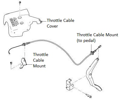
Stock Throttle Cable Reference Diagram
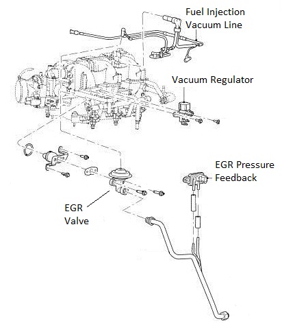
Stock EGR System Reference Diagram
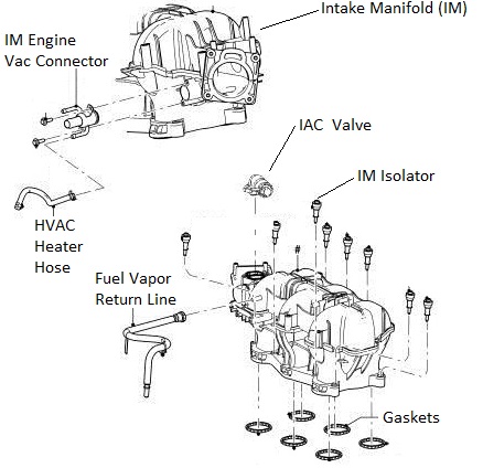
Stock Intake Manifold Reference Diagram
Stock Air Box Reference Diagram

Stock Throttle Reference Diagram

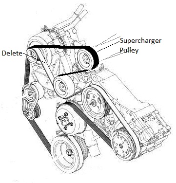
Belt Diagram Reference Diagram (Dark Belt Showing the ModdBox Orientation)

MODDBOX SUPERCHARGER KIT PARTS
ModdBox Supercharger Bypass Valve

ModdBox 255lph Fuel Pump

ModdBox Heat Shield

ModdBox Air Filter

ModdBox Throttle Cable and Cruise Control Mount

ModdBox 3.0 & 3.5 psi Supercharger Pulleys

ModdBox Quick Change Pulley Adapter

ModdBox Plenum Bottom Plate

ModdBox Plenum Top Plate

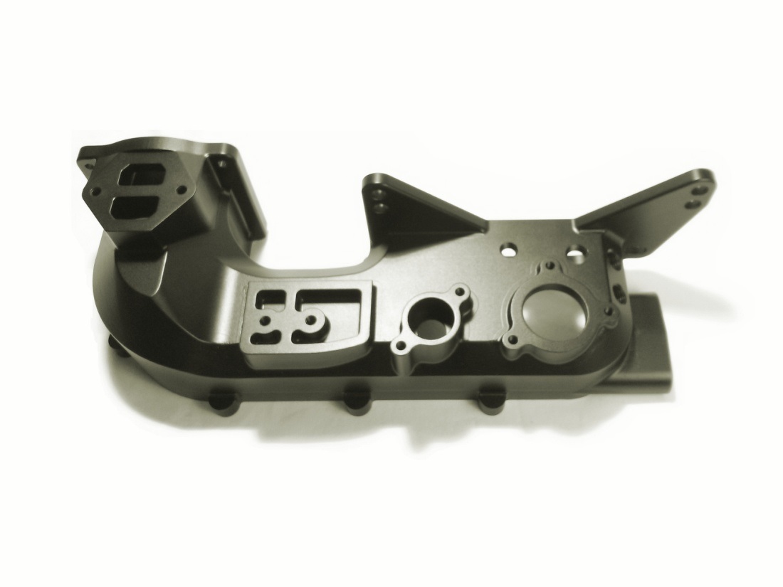
ModdBox Intake Manifold
ModdBox Intake Manifold Top

ModdBox M22-1.5mm EGR Extension

Black Silicone Liquid Gasket

6pk Serpentine Belt

INSTALLATION STEPS
Note: The installation has been broken up into two parts: (1) the fuel pump installation, and (2) the supercharger install.
PART 1 – FUEL PUMP INSTALLATION (3-4 hours)
WARNING: Gasoline vapors are explosive!
Caution: When replacing the fuel pump, perform all work in a well ventilated area away from sparks or open flame. Have a fire extinguisher readily available in case of emergency. Eye protection and rubber gloves are highly recommended. Avoid inhaling fuel fumes. If fuel is ingested, seek medical attention immediately. To avoid a fire hazard, disconnect the negative battery cable when instructed. Failure to perform any service or repair in a safe manner may cause serious personal injury or death.
Relieve the fuel system pressure. This can be done by a variety of methods. It is recommended that you remove the fuel pump fuse and attempt to start your vehicle by using your key. The engine initially turn-over and run, shutter, then stall. Remove your key from the ignition and re-install your fuel pump fuse.
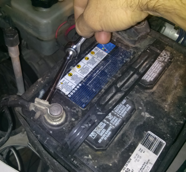
Remove the negative battery cable (1 bolt). Secure it to the side of the battery to prevent any accidental contact with the negative terminal.
Gain access to your vehicle’s fuel pump assembly as required. Use a vacuum and/or a brush and clean off the top of the tank. Caution: Do allow dirt or deleterious substances into your fuel tank.

Disconnect your fuel lines and pry the fuel pump retaining ring tabs back.

Use a flat punch or a large flat head screw driver and rotate and remove the fuel pump retaining ring.

Lift out the fuel pump assembly.

Remove the Stock Fuel Pump Filter.

Un-bolt the ground wire and remove the pump retaining cap.


Unplug the Stock Fuel Pump and disconnect the Fuel Line.

Remove the stock fuel pump and dispose of it appropriately.

Cut the bottom of the Rubber Retaining Gasket so that it can be used as a sleeve for your new 255lph Moddbox Fuel Pump.

File or cut the Stock Fuel Pump Assembly Retaining Cap to accomodate the new 255 lph ModdBox Fuel Pump.

Re-assembly the Fuel Pump Assembly and install the new pump. Reuse the stock fuel line and the provided stainless hose clamp Caution. Do not forget to re-connect the ground wire.

Press the provided In-tank Fuel Filter onto the new fuel pump.

Remove the Stock Fuel Pump Electrical Plug. Install the provided plug for the ModdBox pump by splicing in the wires as shown. Plug in the new Pump and replace the Fuel Pump Assembly and secure the retaining ring. Re-connect your fuel lines.

PART 2 – SUPERCHARGER INSTALLATION (4-5 hours)
Caution: In this procedure, the internal intake ports of your engine will be exposed. Be sure to not drop anything inside these ports or you may very well destroy your engine. Even a small M6 nut or bolt dropped into these ports will likely result in a cracked head and your engine will need to be pulled.
Note: Prior to proceeding, you may want to test your fuel pump installation. If you choose to test the fuel pump installation, be sure to remember to disconnect your battery prior to proceeding.
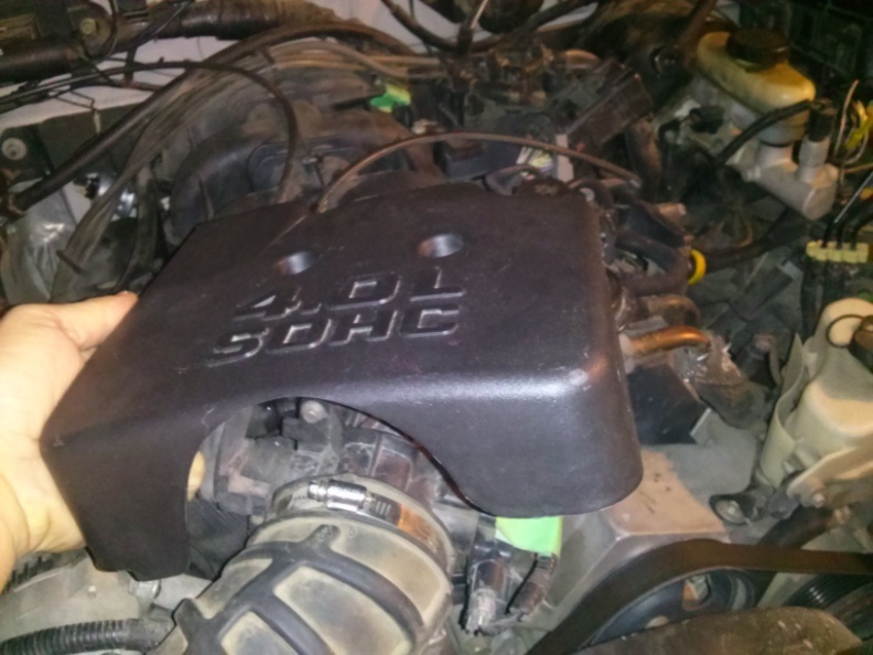
Remove the Throttle Body Cover (2 bolts). If your model is equipped with a second Crank Case Ventilation hose, you will be required to remove the hose clips on the side of the Throttle Body Cover (not shown here).
Loosen the hose clamp and disconnect the Intake Tube from the Stock Air Box Assembly.

Loosen the hose clamp and disconnect the Intake Tube from the Throttle Body.

Disconnect the Crank Case Vent Hose(s) and remove the Intake Tube. Set the Intake Tube aside for later use. Some models have a second Crank Case Vent Hose. For more information, see the Stock Setup Diagrams provided at the beginning of this instruction manual.
Remove the Brake Booster Line from the back of the Intake Manifold. Tape and label if necessary.
Unplug the cable connected to the IAC Valve.

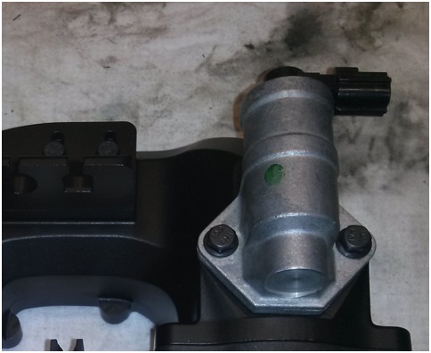
Un-bolt and remove the IAC Valve (2 bolts). Set the IAC Valve aside for later use.

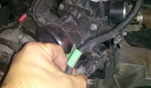
Unplug the Vac line connected to the EGR. Tape and label the Vac Line if necessary.

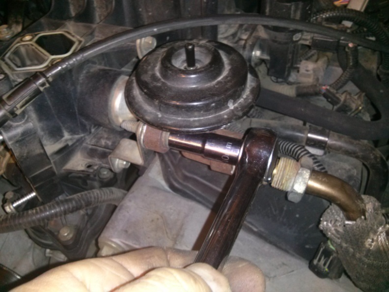
Un-bolt the EGR Valve (2 – 12mm bolts).

Remove EGR Valve by disconnecting the EGR Tube. Set the EGR Valve aside for later use.
Unplug the TPS Sensor. Tape and label the plug if necessary.
Remove the Throttle Cable from the Throttle Body Valve. The cable can be slipped free by manually actuating the valve 90 degrees and providing slack in the cable.

Un-bolt the Throttle Body Valve (4 bolts). Set the Throttle Body Valve aside for later use.

Disconnect the Throttle Cable and the Cruise Control Cable.

Disconnect the electrical wire mount from the left side of the Intake Manifold.
Locate the plastic Radiator Rock Shield located underneath the engine bay. Remove the bolts and set it aside.
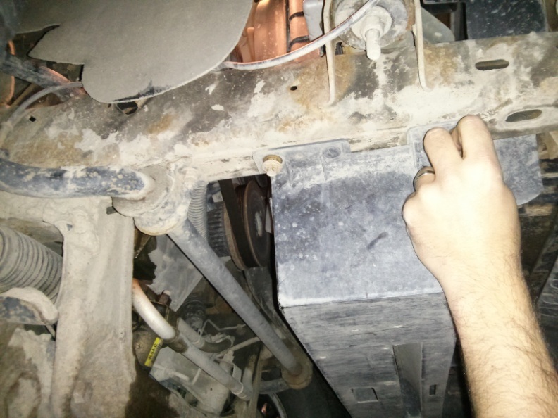
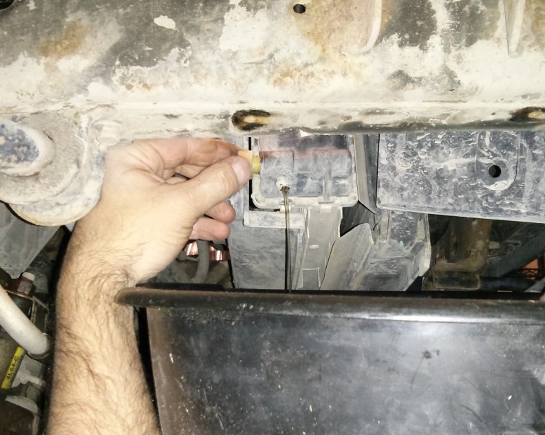
Locate the plastic Radiator Drain Valve at the bottom passenger side of the Radiator. Turn this plug and release only approximately a 3/4 gallon of coolant fluid (~3L). This is to allow the removal and relocation of coolant lines in the following steps.
Remove the HVAC Heater Hoses (2x 1/4” diameter) and the Intake Manifold Engine VAC Line (5/8” diameter) from the Hose Connector Fitting. Tape and label the hoses if necessary.

Locate the 1 5/8” diameter Radiator to Thermostat Coolant Hose.
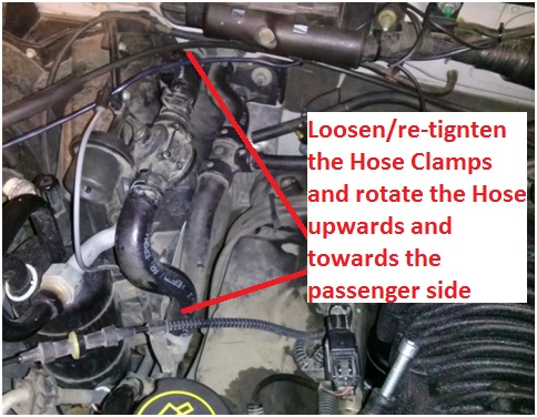
Shorten & re-route the upper radiator coolant hose to be in front (towards front of vehicle) of the Oil Cap and around the AC Line as illustrated. Cut approximately 6” off of the hose and re-secure it to the radiator.
Be sure the hose will not conflict with the belt. If not equipped with AC, secure the hose with restraining straps if necessary. Do not dispose of the 1 5/8” hose. The remaining hose will be needed in a later step.

Remove the Fuel Injection VAC Line located on the right side of the Intake Manifold. Tape and label it if necessary.
Pry off the Ignition Wire Mount located at the top of the Intake Manifold.

Un-bolt the Ignition Wire Flange Mount.

With the Ignition Wire Flange Mount disconnected from the Intake Manifold, proceed to pry the Ignition Wire Flange Mount approximately 2 inches toward the driver side. This additional clearance will aid in the removal of the stock Intake Manifold as well as providing ample space for the future EGR Valve.
Unbolt the Vacuum Regulator (2 bolts) located towards the front drivers side of the Intake Manifold.

Remove the Fuel Vapor Return Line. This fitting is equipped with a simple push-style fitting. Simply push in the large curved shape and the fitting should pull off. The connector on the end of this fitting will not be used. To save time you can simply cut it off near the end of the hose. Label the Fuel Vapour Return Line if necessary.
Remove the Throttle Cable and Cruise Control Cable Mount (2-bolts).

Loosen the Intake Manifold Bolts (12 – T30 Torx bolts). Note that these bolts do not remove completely. Once turned out of the Engine Block, the bolts remain connected to the Intake Manifold. Caution: You do not want to strip the Torx socket on these bolts. It is advisable to inspect the Torx heads and use a vacuum to remove any dirt that may have accumulated inside the head. It may be necessary to use a machinist scribe or similar pointed object to loosen and vacuum out any dirt that may be residing inside the Torx heads before attempting to remove.
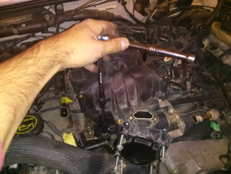
Lift out the Intake Manifold.

Clean the mating face around your engine’s intake ports. Temporarily block these intake ports with paper towel or cloth as shown. Be sure to vacuum out and clean the area to make sure no gravel or other debris can enter into the engine ports.
You are now ready to supercharge your 4.0L.
Caution: The internal rotors of your supercharger have very tight tolerances. Manually rotating the supercharger by hand can cause enough air flow to draw in debris which can cause damage to your supercharger. Be mindful to keep debris away from the internals of your supercharger.
Obtain your Eaton M90 Supercharger (either an 89-93 oval or 94-95 rectangular style M90) and the provided ModdBox Stainless Steel Supercharger Pulley Adapter. Remove the supercharger’s locking flange nut and ensure the shaft key is inserted and aligned. Use a torch to pre-heat the Stainless Steel Pulley Adapter allowing it to thermally expand (If you do not have a torch, simply placing the adapter in a cup of boiling water will expand the adapter enough to proceed). Slip the supercharger Pulley Adapter onto your supercharger shaft until it binds. (Note: The pulley is designed to have an interference fit which will cause the pulley to jam once it slips halfway onto the shaft)

If the threads of the supercharger shaft are not exposed, use a hammer and a socket and Tap the Adapter further down the shaft until the first few threads on the supercharger shaft are exposed beyond the Stainless Adapter bore as shown below. (Note: Do not hit/hammer the Adapter with excessive force. Excessive force may drive the supercharger’s internal coupler an could cause supercharger mis-alignment).

Utilize the stock Eaton M90 Supercharger Lock Nut and two box wrenches. Use one wrench to prevent the Adapter from rotating (utilizing the flats on the stainless steel part) and use the other wrench to apply torque on the Supercharger Lock Nut. Continue to torque down the nut until the back of the Adapter hits the stop on the Supercharger shaft.

Obtain the provided ModdBox 6PK Custom Pulley of your choice and slip it onto the Supercharger Pulley Adapter. Caution: The pulley is a machined precision slip-fit. You must either heat the Pulley or wait for the Adapter to cool prior to slipping it on. NO FORCE SHOULD BE REQUIRED. The pulley will not bind if it is slipped on perfectly straight. It may be easier to torch heat the pulley as this will allow it to slip on with ease.

Rotate the pulley by hand and align the M5 threads with the pulley holes (should rotate freely if slipped on correctly). Torque down the provided M5x16mm socket head cap screws.

Locate the provided Black Liquid Gasket. Apply a thin bead of the gasket to the Eaton M90 Supercharger flange as illustrated.
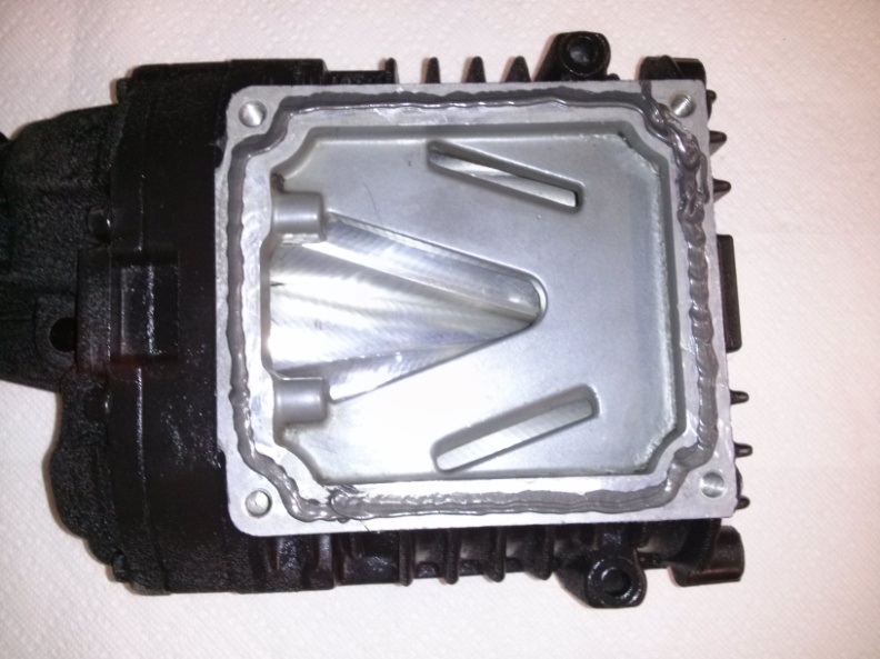
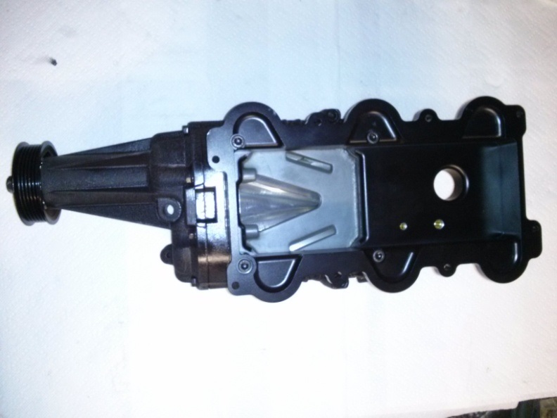
Obtain the ModdBox Plenum Top Plate and bolt it to the base of the Eaton M90 Supercharger & Pulley Assembly. Use the provided M8x40mm socket head cap screws. Clean any excess gasket material.
Use the extra 1 5/8” diameter Radiator Hose that was remaining from a previous step. Measure out and cut a length of hose as is required for your supercharger:
For the 94’-95’ Eaton M90 Supercharger (rectangular inlet): 1-7/8”
For the 89’-93’ Eaton M90 Supercharger (oval inlet): 2-5/8”
Use one of the 2” stainless hose clamps to secure the hose to the Plenum Top Plate. Loosely place the other 2” diameter stainless hose clamp on the hose. Place the entire assembly aside for later use.

Obtain the ModdBox Plenum Base Plate. Apply a generous bead of the provided Black Liquid Gasket around each Intake Port hole as shown. Excess gasket material can be removed in a later step. Caution: Failure to provide enough gasket material in this step can cause future vacuum leaks. Note: Green dots are holes for a an optional intercooler (coolant inlet & outlet ports). The red dot is for an optional IAT/ACT (intake air temperature/air charge temperature) sensor relocation. If these ports will not be used at this time, use the provided brass plugs.
Optional: If you have purchased a ModdBox Intercooler Kit, install the two elbow fittings into the green highlighted locations. Direct the fittings to the rear and connect the 5/8″ diameter coolant lines and route them toward the firewall. Refer to the intercooler installation instructions for further information.
Optional: If you have purchased a ModdBox IAT/ACT relocation kit, install the provided IAT/ACT sensor and wire harness to the red highlighted location as shown below. Connect two wires to the harness using and route them to the front of the vehicle towards the MAF. Refer to the IAT/ACT relocation instructions for further information.

Before placing the Plenum Base Plate on the Engine Block, note the orientation of the lower plenum. The front of the lower plenum has a bulge as shown in the picture below. Caution: The Plenum Base Plate is NOT reversible.

Place the Plenum Base Plate onto the Engine Block in the correct orientation (shown in the previous step). Align the Inlet Ports with the Plenum Bottom Plate holes. Use the supplied M6x35mm socket head cap screws and loosely bolt down the Plenum Base Plate to the Engine Block in a cross pattern (you will need to verify the alignment of the supercharger pulley before tightening the bolts). Use a cloth to remove the excess liquid gasket that squeezes out during the torquing process.

Place and align the Eaton M90 Supercharger and Plenum Top Plate Assembly onto the Plenum Base Plate. Visually inspect the alignment of the supercharger pulley and the other engine pulleys. A miss-alignment of approximately 1/16” is acceptable due to the length of pulley to the adjacent pulleys and the lack of ribs on the idler pulley. If the alignment of your pulley is more than approximately 1/16”, you can fine tune the alignment of the Plenum Base Plate. Simply adjust the Plenum Bottom Plate as required (they are fitted with slotted holes and the assembly can be pushed forward or backwards by approximately 1/8″). Once aligned, torque the M6x35mm SHCS to 12 lbft (17Nm) in a cross pattern. Remove the excess gasket.
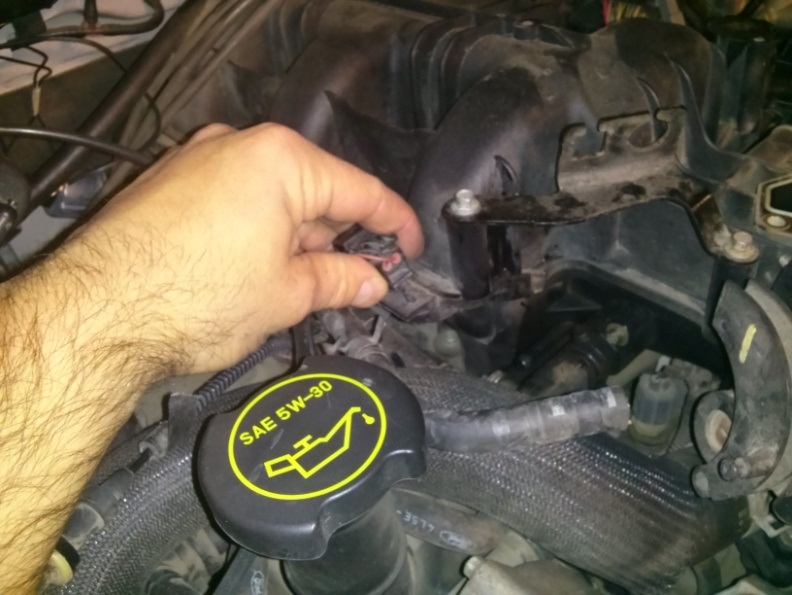
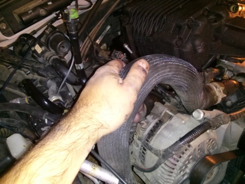
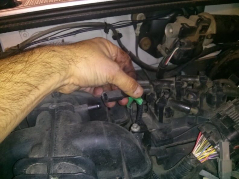
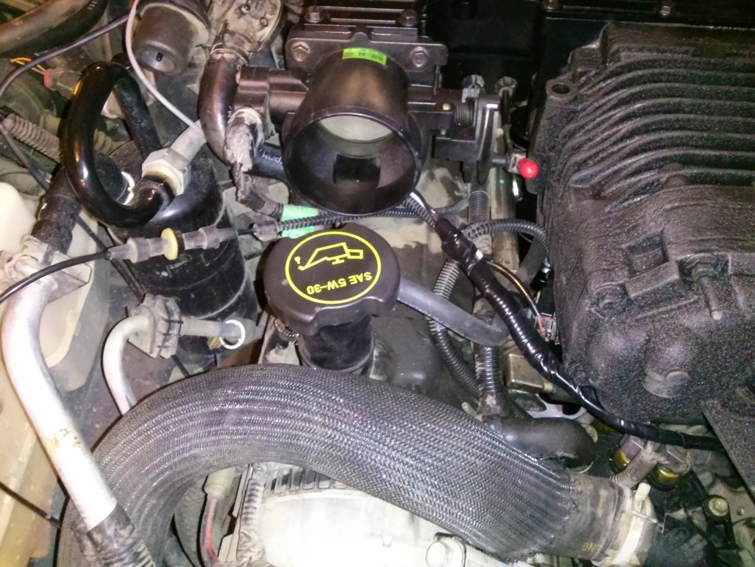
Note the location of the 5/8″ Engine Vac Line & 1/4″ Heater Hose Line. Follow the 5/8″ Engine Vac Line to the firewall and cut it where shown. At this location, it is a hard plastic tube and will need to be saw cut. Remove the remaining 5/8″ Vac line. Note: Disregard the HVAC connector (the part the hand is holding, was located in the stock intake manifold assembly).

Connect the provided 5/8″ Hose to the plastic 5/8″ Vac Line (the one that was just cut in the previous step) and use the provided stainless hose clamp to tightly secure.

Set this 5/8″ Vac hose aside as it will connect to the new Moddbox Intake Manifold (to the threaded hole next to the 35mm bypass valve opening via a 90degree brass barb x npt threaded fitting).
(PHOTO OF MODDBOX MANIFOLD TO BE ADDED)
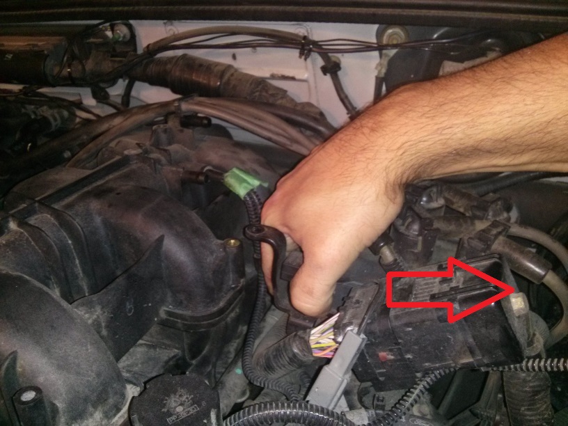
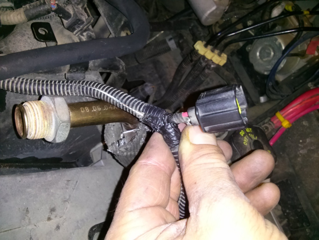
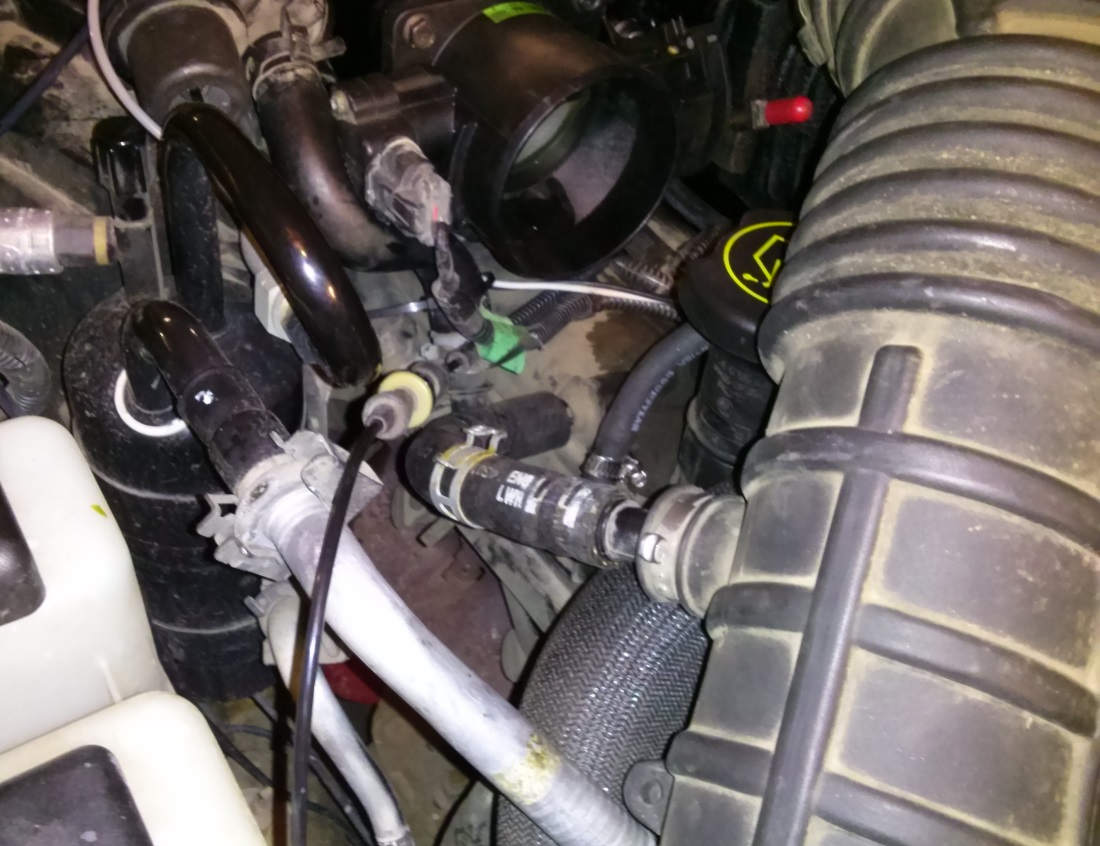
Now locate the 1/4″ diameter HVAC Heater Hose again. The loose end of this 1/4″ HVAC Heater Hose (closer to the front of the vehicle that was previously connected to the stock intake manifold via the HVAC Heater Hose connector – being held by the hand in the photo below), will need to be connected to the coolant barb shown in the next step.
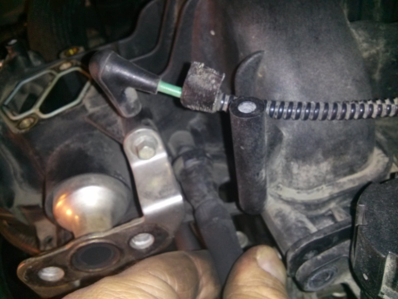
Connect the 1/4″ heater hose to the coolant barb as shown below (it originates from in behind the alternator as illustrated). Remove the existing short hose (previously going to the HVAC Hose Connector that is now abandoned) and replace connect the 1/4″ Heater Hose shown in the photo above. Secure the hose with the provided 1/4″ stainless hose clamp.

Remove the rags or paper towels in your Engine Inlet Ports then proceed with the installation of the Supercharger Assembly. Apply a thin bead of Black Liquid Gasket along the Plenum Base Plate (already aligned and bolted to the Engine Block). Caution: Be sure to apply gasket material around all the bolt holes (as illustrated in the photo below). The gasket material must be extended to the inside edge of the mating face as shown on the bottom-left of the photo below. Failure to do so can result in a leak in your Intake Manifold Assembly. Note: The liquid gasket is a bit messy. Although we own a laser engraver and could easily cut you some nice gaskets for this application, the liquid gasket is much better and provides a much better seal.

Remove temporary engine rags/paper towels placed in the engine’s inlet ports.
Obtain the Eaton M90 Supercharger Assembly (already assembled in a previous step). Place the assembly onto the Plenum Base Plate and bolt it down with the provided M6x30mm Hex Bolts (they come with washers). Caution: You may want to place a paper towel or cloth temporarily into the 1 5/8” hose as shown below on the Plenum Top Plate. This will keep you from accidentally dropping something into your engine’s intake ports.
Install the provided NPT plugs into the threads on the upper plenum (the two brass fittings shown in the above photo).
Optional Step. The provided threaded NPT ports have been included for the installation of a Boost Sensor and/or Manifold Temperature Sensor. If you have purchased monitoring equipment from ModdBox (or a third-party), it is advisable to install the necessary fittings now. Once the Intake Manifold is installed, these ports are less accessible and some dis-assembly may be required.
Obtain the ModdBox Intake Manifold (shown below). Install the three provided 1/4″ NPT x 3/8″ barbs. Use the provided M5x16mm socket head cap screws and bolt the Supercharger Bypass Valve to the ModdBox Intake Manifold.
(PHOTO OF MODDBOX INTAKE MANIFOLD c/w BARBS & 5/8″ ELBOW & BYPASS VALVE INSTALLED)
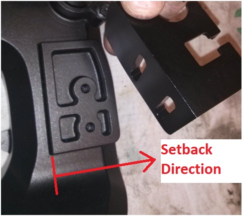
Install the ModdBox Cruise Control/Throttle Cable Mount to the Moddbox Intake Manifold. Use the provided M6x12mm socket head cap screws. Note: For models with newer throttle cables, the mount can be aligned with the base (factory offset). However, older models vehicles should be setback approximately 1/8” to 1/4” back to compensate for the creep (stretching) in the throttle cable. You may want to leave these bolts loose to allow for easy adjustment later.
Install the stock IAC Valve on to the ModdBox Intake Manifold using the M6x12mm socket head cap screws.
Optional Step. A 1/8”NPT port has been provided for a Water/Methanol Injection Nozzle. If you have purchased a ModdBox Water/Methanol Injection Kit (or a third party kit), it is advisable to install the necessary fittings now. Once the Intake Manifold is installed, these ports are less accessible and some disassembly may be required.
(PHOTO OF MODDBOX METHANOL INJECTION PORT TO BE ADDED)
Proceed with the ModdBox Intake Manifold installation by adjusting the illustrated hoses as described below.

Clear the future Throttle Cable and Cruise Control Cable location of any loose hose, ignition cables, electrical wires, fittings, etc. Be sure to fasten these components securely and away from the action of the throttle body. Caution: Failure to keep this area clear could result in your throttle sticking open! Be sure this area is kept clear and that all components in the engine bay are kept secure.

Connect the 5/8″ Vac Line from a precious step to the 90 degree brass elbow on the Moddbox Intake Manifold (next to the bypass valve). Locate the Stock Throttle Cable and Cruise Control Cable (if equipped). Connect the cables to the ModdBox Cable Mount as illustrated. Snap-in the Throttle Cable to the slot on the passenger side. The Cruise Control Cable must be snapped into the driver side slot. DO NOT apply liquid gasket or install your throttle body at this point. Note: Contrary to the photo, it’s easier to bolt on the Throttle Body after the assembly is bolted to the supercharger.

Locate your Throttle Position Sensor Plug and Idle Air Control Valve Plug.
Carefully expose the wires from the plastic guard and electrical tape.

Take the Idle Air Control Valve Plug Wire and cut it approximately 3” from the plug end. Splice in approximately 3’ of wire to extend the wire to the new IAC location and plug it in. Use the provided tie-downs to secure the wire away from any moving parts. Caution: Make sure you do not reverse the polarity of the wires. This will result in your vehicle going to full throttle as soon as you start your vehicle if not connected correctly.

Apply the supplied Liquid Gasket to the ModdBox Intake Manifold as illustrated. Note: Install throttle body after you bolt the manifold to the supercharger.

Remove temporary cloth in the rear bypass opening (if placed). Line up the 1 5/8” Supercharger Bypass Hose and press the assembly down. Secure the 2” Hose Clamp to the Supercharger Bypass Valve. Note: It is easiest to have the tube connected to the Plenum Top Plate (as instructed in an earlier step) contrary to what is illustrated in the photo (the 1 5/8″ tube is connected to the intake manifold in the above photo).

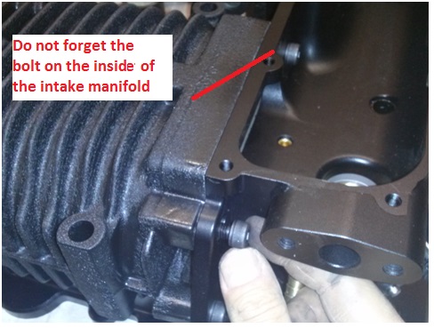
Bolt down the ModdBox Intake Manifold Assembly to the back of the supercharger using the provided M8x25mm socket head caps screws.

Use the custom washer when placing this M6x25 bolt (the square shaped washer with the offset hole). You will be required to use some liquid gasket to ensure it is air-tight. Caution: Failure to install the washer will result in a vacuum leak.
Bolt the Stock Throttle Body onto the Intake Manifold as shown using the provided M6x16mm socket head caps screws.

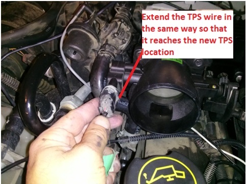
Locate the TPS plug wire and cut it approximately 3” from the plug end. Splice in approximately 3’ of wire to extend the wire to the new IAC location and plug it in. Use the provided 1/4″ loom and the tie-downs to secure the wire away from any moving parts. Caution: Make sure you do not reverse the polarity of the wires.
Place a thin bead of Black Liquid Gasket on the ModdBox Intake Manifold’s mating face as illustrated.

Place and bolt up the ModdBox Intake Manifold Cover with the provided M6x12mm socket head cap screws.

Locate and connect the Brake Booster Hose to the provided 3/8” barb located on the back driver side of the ModdBox Intake Manifold.

Locate the Fuel Injection Vac Line and connect it to the 3/8” barb located beside the Supercharger Bypass Valve.


Locate the Fuel Vapor Return Line. Cut off the press fit connection and reconnect it to the remaining 3/8” barb on the ModdBox Intake Manifold. Secure the hoses with the provided hose clamps.


Locate the Stock EGR Valve. You must first torque the male end of the provided Stainless Steel EGR Extension to the valve prior to installing on the vehicle. Caution: The Stainless Steel EGR Extension is not designed to be twisted. You must first torque the male end to the valve prior to installation thereby allowing the female end to swivel freely during installation. Do not twist the EGR Extension when tightening the threads or damage to the extension may occur. Note: Some models are not fitted with EGR. For these models, a block plate and applicable hardware are included.

Use the provided M8x25mm bolts and secure the EGR Valve to the ModdBox Intake Manifold as illustrated. Then connect the female end of the EGR Extension Cable to the stock EGR pipe. Use the female swivel connection to torque the connection tight. Bend the the EGR Extension pipe to suit.

Reconnect the EGR Vac Line.

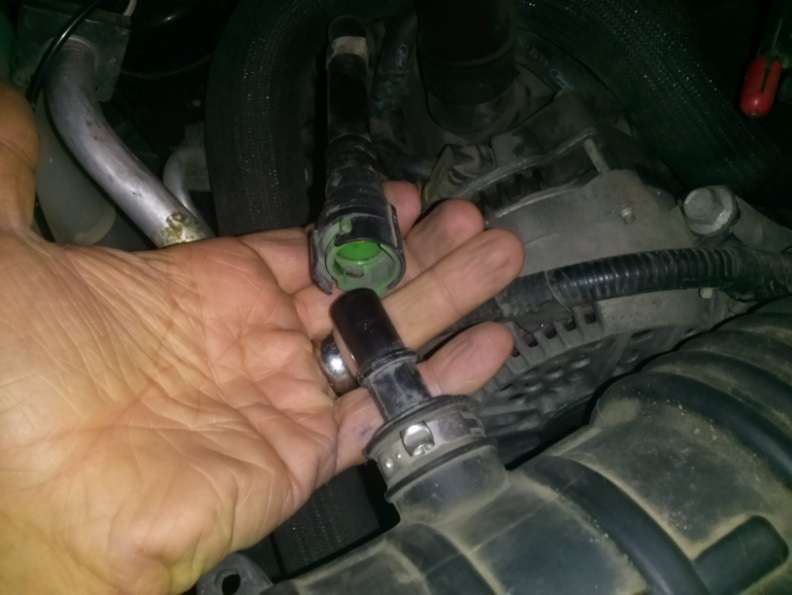
Use the provided 5/8” hose (16” long) and connect one end to the Crank Case Ventilation Tube. The Stock Crank Case Ventilation Tube can be removed by pressing the plastic spring release on the end of the fitting.

Connect the other end of the Crank Case Vent Hose to the Stock Intake Tube. Use the provided elbow and insert it into the Stock Rubber Intake Hose. This will alleviate any bending on the crank case ventilation hose. Note: Contrary to the photo, the 5/8″ barb x barb 90 degree elbow included in the kit should be installed in the stock intake tube port (remove existing straight fitting on stock tube).
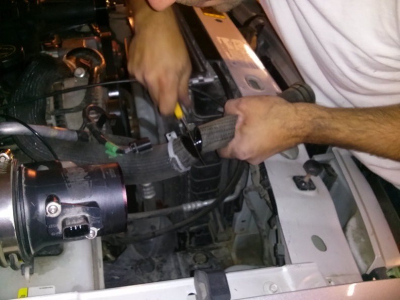
For 2004-2011 Rangers Only: Remove your vehicle’s Stock Airbox Assembly (see stock diagrams for more details). Use a saw to cut the Stock MAF Tube approximately 1” in front of the MAF mount. Re-connect the MAF tube to the Stock Intake Tube. Plug the MAF back into the electrical socket. See illustration below.
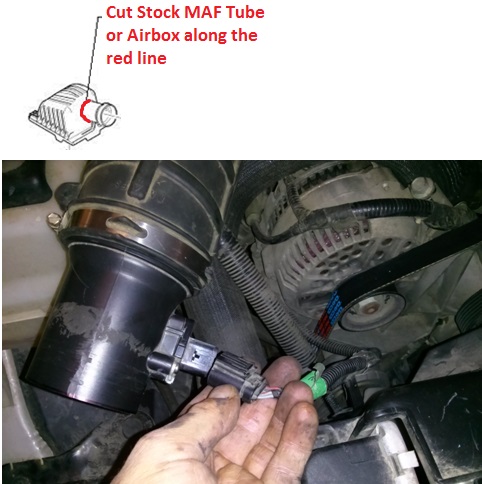
(Note: Does not apply to models equipped with a flange between the airbox and the MAF )
For all other models: Unbolt your MAF housing from your stock airbox. Re-connect the MAF housing to the Stock Rubber Intake Hose and plug in your MAF plug.
Connect the downstream side of the Stock Intake Tube to the Throttle Body. Secure both hose clamps.

Optional. Your oil cap is easily accessible but it will rub against the stock Intake Tube when you perform maintenance. Although this is minor, you may want to extend the oil cap. Did you know your oil cap has already been extended upwards with a 2.5” extension? You may want to buy an additional extension to raise it up another 2.5” to clear the Intake Tube. See illustration below. Note: You may also prefer the Ford Engine Oil Filler Tube off the 4.6L Explorer. It is longer and has a 45 degree bend which you could eliminate your stock extension.

(Optional Ford Part #: ML5E-6765-AA – Straight Ford Ranger Extention)
Bolt the ModdBox Intake Heat Shield to the bolt located behind the passenger side headlight assembly. If equipped with the bolted connection, bolt the Intake Adapter Flange to the MAF assembly as shown. If not equipped with the intake bolted connection, connect the Air filter to the modified MAF assembly.

Secure the Intake Shield to the radiator coolant hose with the provided strap. Place your 70mm ModdBox Cold Air Intake Filter to the Stock MAF Tube and secure the hose clamp.
Re-install Radiator Rock Shield. Replace the 3/4 gallon (~3L) of coolant back to into the radiator cap.
Slack your Belt Tensioner using a 3/8” Box Wrench or Belt Removal Tool. Remove the Stock belt and replace it with the ModdBox 6PK Belt as illustrated below.
Optional. Obtain your stock throttle body cover. Cut the cover as shown in the below diagram. Remove one M6 bolt from your ModdBox Intake Manifold Cover and bolt down the throttle body cover.

Reconnect your vehicle’s negative battery cable.
Finally, the last step required is to wait 24 hours. You must allow the liquid gasket material to fully cure at room temperature or as per the manufacturer’s recommendations. Failure to provide the necessary curing time may lead to vacuum leaks.
CONNECTION CHECK LIST
EGR Vac Line to EGR Valve
EGR Stainless Recirculation Line (if equipped)
Crank Case Vent Hose to Intake Tube (may be 2 depending on your model)
IAC Electrical Plug (may need to check polarity on the wiring extension)
TPS Electrical Plug (may need to check polarity on the wiring extension)
Throttle Cable is Connected
Cruise Control Cable is Connected
Throttle Cable & Cruise Control Mount is Adjusted
Electrical extension wires are secured away from the Throttle Cable and Cruise Control cables. Caution: Failure to verify obstruction-free operation of the throttle cable and cruise control cables could result in malfunction of your vehicle’s operation.
Fuel Vapor Return Line
Fuel Injection Vacuum Line
Brake Booster Vacuum Line
INITIAL DRIVING & TUNING INSTRUCTIONS
Running the 3.4″ boost pulley
You must use 91+ octane fuel. Moddbox testing has proven that the stock ecu & injectors of a healthy vehicle are capable of providing adequate fueling with 91 octane while using the provided 255lph fuel pump and low boost pulley. Up to the 3.5 psi boost (3.4″ pulley), you will not be required to upgrade your injectors or make changes to your MAF while tuning; however, it is recommended that you install an A/F gauge to safely monitor your fuel.
Running the 3.15″ or smaller boost pulleys
At minimum, you will require the installation of larger injectors (suggest 39+lb/hr), colder plugs (suggest 1 heat range colder with 0.035″ gap – ex NGK TR6GP), and an ecu remap. Moddbox makes this easy by offering these tuning services through our affiliate online tune shop at Lasota Racing. We also sell an SCT firewire to PLX module cable and a compatible A/F Module & Gauge Combo Package that makes tuning easy. For more information, please contact us at [email protected].
Starting Your Vehicle for the First Time
Caution: Be sure you have waited for 24hrs for your liquid gasket material to fully cure prior to proceeding.
If you are unsure about whether you have correctly installed everything described in this manual, please spend some time to review the instructions and consult the “connection check list”.
Once the checklist has been consulted… it’s time to turn the key :) Your vehicle should start up exactly as it did before. It may however turn over once before starting if the fuel lines where not fully primed. If your vehicle idles rough, you have probably missed a vacuum line. Consult the installation steps above.
RECOMMENDATIONS
We recommend either installing either Methanol Injection or an Intercooler Kit for all boosts above 3.0 psi. Forced induction adds heat to the intake air as a result of compression. This added heat can increase your exhaust gas temperatures (EGTs) during extremely harsh driving conditions. These EGTs could adversely affect your vehicle. This risk can be mitigated by installing cooling equipment (intercooler or methanol injection). You can also further mitigate this risk by installing an EGT gauge and ensuring that you do not push your vehicle beyond 870 degC (1600 degF).
It is a good idea to change your spark plugs. Although you are not required to change your spark plugs, Moddbox recommends running spark plugs that are one heat range colder than stock. It is also recommended that you gap your plugs at 0.035″.

TROUBLESHOOTING COMMON PROBLEMS
Idle is Erratic
If your idle rises and falls in a repeating pattern, you have a massive Vacuum leak. One of the items on the connection list was likely missed.
High Idle
It is likely that you installed your IAC valve backwards or reversed the polarity of your IAC wiring.
Truck makes a whistle sound when driving
You probably have a kink in your crank case ventilation hose or a vacuum leak.
Squealing Pulley
The removal and replacement of a new belt may have caused your worn idler pulley to start squealing. Apply lubrication or replace your idler pulley.
Thank you for choosing Moddbox! We would love to hear how we can make this installation manual better. If you feel we could improve the installation manual in any way, please let us know by emailing us at [email protected].
Submit your build photos! We love seeing your builds. Please submit your Name, State/Province, and some photos of your vehicle and we will add you to our customer build section.